Thermistor Wiring: Polarity, Lead Resistance and Connectors
Oct 15, 2026Updated October 15, 2026. Reviewed by the Focusens Engineering Team.
| What happens in the wiring | Effect on a 10 kΩ NTC reading | Size (our calculation, B 3977 K) |
|---|---|---|
| Leads swapped | None | 0 °C |
| 30 m of 24 AWG cable added | Reads colder | 0.01 °C at 25 °C, 0.15 °C at 85 °C |
| 10 Ω of bad contact or crimp | Reads colder | 0.02 °C at 25 °C, 0.30 °C at 85 °C |
| Open joint or broken lead | Reads the lowest temperature or an open-circuit fault | Not a number |
| Short between the leads | Reads the highest temperature or a short-circuit fault | Not a number |
| Measuring current (self-heating) | Reads warmer | 0.04 °C at 0.1 mW, 0.25 °C at 0.63 mW (5 V, 10 kΩ divider) on a 2.5 mW/°C probe |
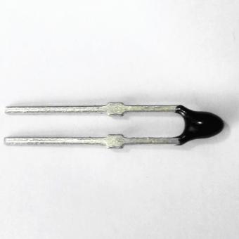
A two-lead NTC or ceramic PTC thermistor has no polarity. It is a resistor whose value changes with temperature, so current can flow through it in either direction and the reading is the same. Silicon KTY sensors, sold as linear PTC thermistors, need a check. KTY83 and KTY84 are single-chip parts whose published curve holds only with the current in the right direction, and genuine parts carry a colored band to mark it; KTY81 and KTY82 use two chips in series opposed and work either way round (see how to test a KTY84-130 with a multimeter). Carrier puts it directly in the installation manual for its immersion thermistors: "These Carrier thermistors and RTD temperature sensors are both non-polarity and non-position sensitive." The same manual gives the lead colors only as part of the sensor type, "10 KΩ nominal (White/Green)", with no plus or minus lead. Murata answers the same question for its PTC chip thermistors in a product FAQ: "There is no polarity."
Some thermistor probes do have assigned wires. A probe with a built-in bridge resistor, or two elements sharing a common lead, is no longer a plain two-terminal part. The Apogee SF-110 manual, for example, gives each conductor a function, such as "positive leaf thermistor lead" and "negative leaf thermistor lead", and puts precision bridge resistors in the cable, so its wires are not interchangeable (Apogee SF-110 manual). If a probe has more than two conductors, read its drawing before connecting it. If it has exactly two and the element is an NTC or a ceramic PTC, polarity is not the problem.
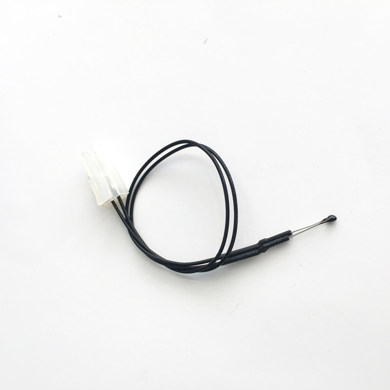
A thermistor connection is two wires. On a controller or logger with a thermistor input, the two leads go to the two input terminals in either order, and the input is set to the matching curve (R25 and B value, or Type 2, Type 3 or 3950). On a bare analog input, the thermistor is wired in series with a fixed resistor and the controller reads the voltage at the junction. That voltage divider is what "thermistor circuit" usually means:
This also answers "are thermistors wired in series": the NTC sits in series with the fixed resistor on the board, and any cable or contact resistance sits in series with the NTC.
The measuring current heats the thermistor slightly, so it reads warmer. The heating in °C is the power divided by the probe's dissipation factor. Focusens product pages list a dissipation factor of at least 2.5 mW/°C for our MFP-1 probes and MFP-2 ring-lug probes, so 0.1 mW in the thermistor raises it by up to 0.04 °C. Murata sets "0.1°C as the upper limit of self-heating" when it rates operating current (Murata FAQ). YSI gives a dissipation constant of 1 mW/°C in still air for its epoxy-encapsulated 44000 series thermistors, against 8 mW/°C in a well-stirred oil bath (YSI catalog), so the same power heats an unmounted thermistor in still air about eight times more than in oil.
For a 10 kΩ NTC at 25 °C, 0.1 mW means about 100 µA or 1 V across the thermistor (our calculation). A divider with a 10 kΩ fixed resistor puts more than that into the part: at 25 °C, 0.27 mW from a 3.3 V supply and 0.63 mW from 5 V, which is 0.11 °C and 0.25 °C of self-heating on a 2.5 mW/°C probe (our calculation). That is acceptable in a stirred liquid and worth checking in still air.
Lead resistance makes an NTC thermistor read colder, because the controller sees the thermistor plus the wire and a higher resistance means a lower temperature on an NTC curve. The BIPM thermometry guide gives the size of the error as the lead resistance divided by the thermistor's sensitivity, and notes that the error "is largest at high temperatures" (BIPM-CCT Guide on Secondary Thermometry: Thermistor Thermometry). The same guide calls a 2-wire measurement "satisfactory" for many thermistor uses, because thermistors have high resistance and a steep slope.
The table puts numbers on that for a 10 kΩ NTC with B25/85 = 3977 K, the value of the Vishay NTCLE100E3 10 kΩ part. B values are explained in our NTC thermistor guide.
| Temperature | NTC resistance (Beta model) | Slope | Error from 1 Ω in series |
|---|---|---|---|
| 0 °C | 33,900 Ω | −1,807 Ω/°C | −0.0006 °C |
| 25 °C | 10,000 Ω | −447 Ω/°C | −0.0022 °C |
| 50 °C | 3,563 Ω | −136 Ω/°C | −0.0074 °C |
| 85 °C | 1,070 Ω | −33.2 Ω/°C | −0.030 °C |
| 100 °C | 685 Ω | −19.6 Ω/°C | −0.051 °C |
Our calculation with the Beta equation, R25 = 10 kΩ and B = 3977 K. The Beta equation matches the part at 25 and 85 °C and drifts away from those points: Vishay's data sheet gives 32.55 kΩ at 0 °C, not 33,900 Ω, and our Type 2 table lists 32,651 Ω. The error per ohm moves by less than 0.001 °C at every temperature in the table. A 10 kΩ part with B = 3435 K gives −0.0026 °C per ohm at 25 °C and −0.026 °C at 85 °C, so the conclusion holds across common 10 kΩ curves. Full resistance tables for Type 2, Type 3 and 3950 parts are in our 10k thermistor chart.
Cable resistance comes from the copper. The NIST copper wire tables (NBS Handbook 100) give 53.2 Ω/km for 22 AWG, 84.2 Ω/km for 24 AWG and 135 Ω/km for 26 AWG at 20 °C. Both conductors carry the current, so the resistance added is twice the cable length times that figure.
| Cable (two conductors) | Added resistance | Error at 0 °C | Error at 25 °C | Error at 85 °C |
|---|---|---|---|---|
| 10 m of 24 AWG | 1.7 Ω | −0.001 °C | −0.004 °C | −0.05 °C |
| 30 m of 24 AWG | 5.1 Ω | −0.003 °C | −0.011 °C | −0.15 °C |
| 30 m of 26 AWG | 8.1 Ω | −0.004 °C | −0.018 °C | −0.24 °C |
| 100 m of 24 AWG | 16.8 Ω | −0.009 °C | −0.038 °C | −0.50 °C |
| 30 m of 24 AWG on a 2252 Ω NTC | 5.1 Ω | −0.013 °C | −0.051 °C | −0.65 °C |
Our calculation from the NBS resistance values above and the Beta equation. The 2252 Ω row uses B = 3891 K from the YSI thermistor catalog and is approximate.
For a 10 kΩ NTC measuring room or water temperature, ordinary cable runs do not matter: 30 m of 24 AWG wire costs about a hundredth of a degree at 25 °C and less than 0.06 °C at 60 °C. The error becomes real when three conditions stack up: a hot sensor (low resistance), long or thin wire, and a low-value part such as a 2252 Ω NTC, which carries more than four times the error of a 10 kΩ part on the same cable. The BIPM guide puts it the same way: lead resistance "can become a problem at higher temperatures when the thermistor resistance is low".
| Sensor temperature | Loop resistance for a 0.1 °C error | 22 AWG | 24 AWG | 26 AWG |
|---|---|---|---|---|
| 25 °C | 44.9 Ω | 421 m | 266 m | 166 m |
| 50 °C | 13.6 Ω | 127 m | 80 m | 50 m |
| 85 °C | 3.3 Ω | 31 m | 19 m | 12 m |
| 100 °C | 2.0 Ω | 18 m | 11 m | 7 m |
Longest two-conductor cable, rounded down to the whole meter, that keeps the error on a 10 kΩ, B 3977 K NTC under 0.1 °C. Our calculation from the NBS solid-copper values at 20 °C; NBS notes that stranded conductors run 2 to 5 percent higher, so leave some margin.
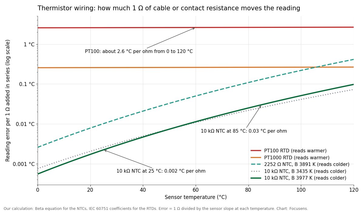
Compared with an RTD, thermistor wiring is forgiving. One ohm in series costs a PT100 about 2.6 °C, which is why RTDs are wired with 3 or 4 wires (see RTD wiring: 2, 3 and 4-wire and RTD lead resistance error). The same ohm costs a 10 kΩ NTC at 25 °C about one thousandth of that.
A sound connector adds almost nothing: JST's XH series catalog specifies a contact resistance of 10 mΩ maximum when new and 20 mΩ after its environmental tests, which on a 10 kΩ NTC is below 0.002 °C even at 85 °C. A degraded joint can add more resistance than the whole cable run. Molex's Quality Crimp Handbook warns: "Over-crimping a crimp termination will reduce the circular area of the conductor and increase resistance." It adds that a crimp must break down surface oxides, or "resistance can increase."
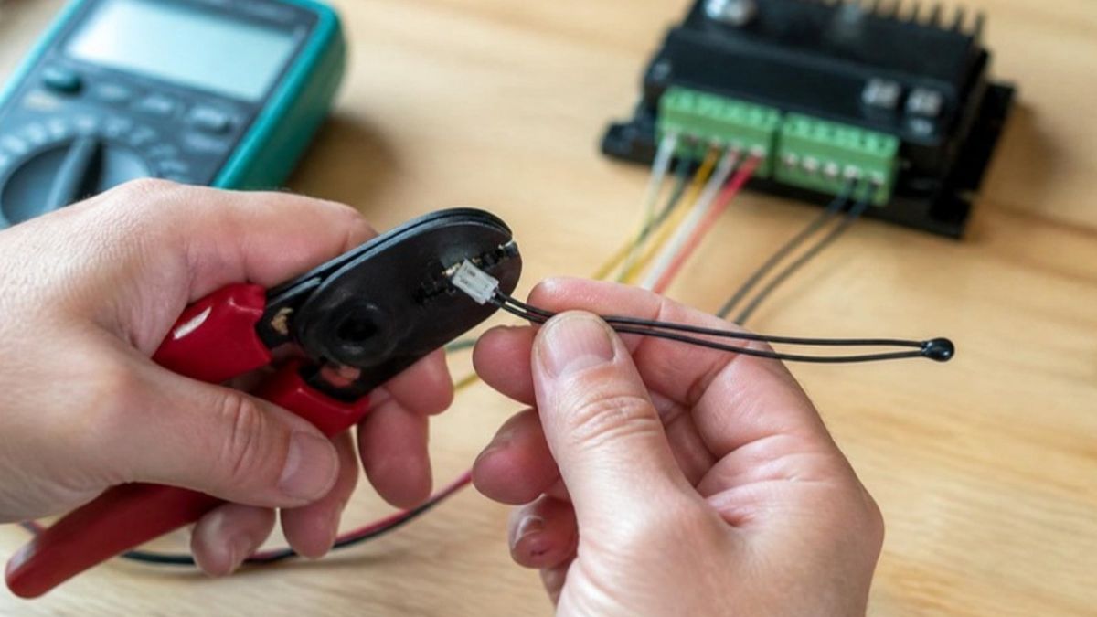
How far a degraded contact moves the reading depends on how bad it gets. These values are illustrative, not measured on a failed part:
| Resistance added by the joint | Error at 0 °C | Error at 25 °C | Error at 85 °C |
|---|---|---|---|
| 0.04 Ω (two XH contacts at their 20 mΩ limit) | 0.000 °C | −0.0001 °C | −0.001 °C |
| 1 Ω | −0.0006 °C | −0.002 °C | −0.03 °C |
| 10 Ω | −0.006 °C | −0.02 °C | −0.30 °C |
| 100 Ω | −0.06 °C | −0.22 °C | −2.9 °C |
Our calculation for a 10 kΩ, B 3977 K NTC.
The same arithmetic explains why connectors matter most on very hot sensors. A 100 kΩ, B 3950 K thermistor at 250 °C is down to about 335 Ω, so each ohm in a connector moves the reading by about 0.2 °C and a 10 Ω bad contact by about 2 °C (our calculation, approximate because the Beta equation is stretched that far from 25 °C).
A joint that opens completely reads as near-infinite resistance, and the controller shows its lowest temperature or an open-sensor fault. Carrier's troubleshooting table lists the three patterns: "Sensor reads infinity/very high resistance" means the sensor or wires are open, "Sensor reads low resistance" means they are shorted, and "Erratic readings" point to bad wire connections (Carrier immersion thermistor manual).
Three checks for connector faults:
On a 10 kΩ NTC, a long cable is more likely to add noise than a meaningful resistance error. A reading that is steady on a short lead and jumps around on a long run points to interference coupled into the cable. Routing, twisted pair or shielded cable and a filter at the input deal with that; thicker wire does not. Apogee recommends shielded twisted pair for extensions "in order to minimize electromagnetic interference" (Apogee SF-110 manual).
Carrier's wiring rules for its immersion thermistors cover the rest (Carrier immersion thermistor manual):
Apogee reports that its SF-110, which has its bridge resistors built into the cable, shows negligible effect from up to 100 m of added cable when the measuring input impedance is 1 MΩ or higher. The same manual warns that this cable "should not be shortened, otherwise the bridge resistor will be removed" (Apogee SF-110 manual).
Insulation leakage works in the opposite direction to lead resistance. Leakage between the two conductors shunts the thermistor and makes it read warmer, and it matters most when the thermistor resistance is highest, at low temperature. With the 100 MΩ minimum insulation resistance on our probe data sheets, a 10 kΩ NTC at 0 °C reads about 0.006 °C warm (our calculation), close to the BIPM guide's own example. Wet or damaged insulation can fall far below 100 MΩ. At 1 MΩ the same NTC reads about 0.6 °C warm at 0 °C and 1.7 °C warm at −20 °C (our calculation), which is why a probe with water in its cable drifts warm in the cold.
The thermistor element always has two terminals. A probe with three or four wires has added something, and the extra conductor is usually one of these:
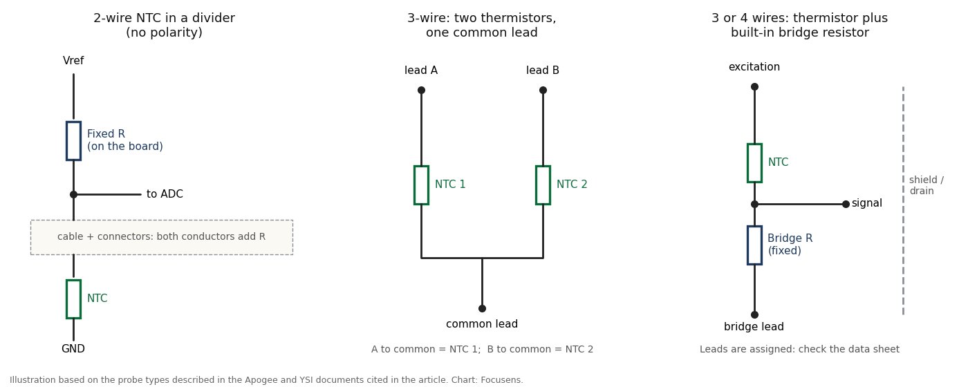
So "does a three wire thermistor have a resistance" has a practical answer: measure all three pairs. On a dual-element probe, each outer lead reads one thermistor's value against the common lead. On a probe with a bridge resistor, one pair reads a fixed value that does not change with temperature; Apogee's troubleshooting section expects 24.9 kΩ on that pair. A shield or ground wire reads open. If one pair reads close to 0 Ω and the other two read about 110 Ω (or about 1,100 Ω) at room temperature, the probe is a 3-wire PT100 (or PT1000) RTD, not a thermistor: its two same-color leads join at one end of the element. RTDs are the parts usually supplied with three leads. Carrier's immersion sensor manual says "All thermistor type units are supplied with (2) flying lead wires, and all RTD’s are supplied with (2) or (3) flying lead wires". Our RTD wiring guide covers that case.
Motor protection PTCs are wired differently from measuring NTCs because they switch a relay rather than report a temperature. Siemens describes the most frequent arrangement in its SIRIUS 3RN2 manual: one PTC sensor in every winding overhang, "connected in series", with the measuring circuit "routed as separate control cables". The same manual says cores of the motor power cable must not be used for it.
ZIEHL's MS220KA manual sets two wiring limits that matter for cable choice:
Trip values, sensor counts per relay and the insulation-test warning are in motor PTC thermistor wiring and trip values, and the DIN resistance limits are in our DIN 44081 and DIN 44082 guide.
A thermistor can be extended with ordinary stranded copper wire. No special alloy is needed, unlike a thermocouple, which needs matching extension wire (see cold junction compensation). The choices that matter are:
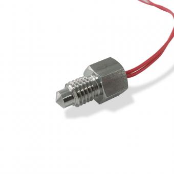
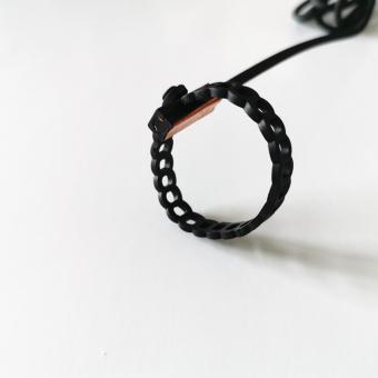
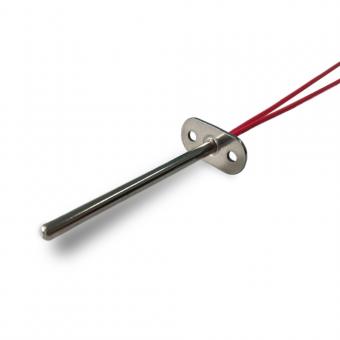
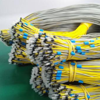
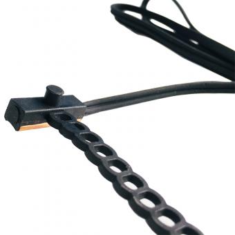
Focusens builds NTC probes and the cable assemblies behind them: epoxy, glass and ring-lug surface NTC sensors in our NTC thermistor probe range, and complete harnesses with connectors in our cable assembly range. The MFP-2 ring-lug series is also offered as a 3-wire version; as with any probe with more than two conductors, check which lead is which on the drawing for your order. For a quote, send us the R25 and B value, the cable length and gauge, the jacket material and the connector.
A two-lead NTC or ceramic PTC thermistor can be wired either way round. It is a resistor without polarity: Carrier states this for its immersion thermistors and Murata for its PRF series PTC chips. There are two exceptions. Silicon KTY83 and KTY84 sensors are polarized, and probes with three or more wires have leads with assigned functions that must follow the drawing.
Thermistor wires can be extended with plain copper wire. For a 10 kΩ NTC, 30 m of 24 AWG adds about 5 Ω, which shifts the reading by roughly 0.01 °C at 25 °C and 0.15 °C at 85 °C (our calculation). Make a sound splice and keep the run away from line-voltage wiring.
For a 10 kΩ NTC, 22 to 26 AWG is enough for most runs; Carrier recommends 16 to 26 AWG twisted pair or shielded cable for its immersion thermistors. Use heavier wire only for long runs to a hot sensor or for low-value thermistors around 2 kΩ, where lead resistance has more than four times the effect.
A three-wire thermistor probe has a resistance on each pair of leads. Measure all three pairs: two elements sharing a common lead each read their own value, a built-in bridge resistor reads a fixed value, and a shield reads open. If one pair reads near 0 Ω and the other two read about 110 Ω at room temperature, the part is a 3-wire PT100 RTD.
If the reading is off by whole degrees, check the curve first. Carrier's troubleshooting table tells installers to "Verify controller is setup for correct sensor curve", and a wrong curve moves the reading by degrees: a Type 2 sensor on a Type 3 input reads about 2 K low at 0 °C and about 7 K high at 100 °C (see our 10k thermistor chart). Series resistance from a long thin cable, a poor crimp or a corroded connector also makes an NTC read low, but on a 10 kΩ part it takes about 100 Ω to move the reading by 3 °C at 85 °C (our calculation). A reading that is too high can come from self-heating or from moisture leakage in the cable at low temperature.
No special alloy is needed. Plain copper works for NTC and PTC thermistors alike. Motor protection PTCs do need their own control cable: Siemens does not permit "cores from the power supply cable of the motor", and ZIEHL limits the line resistance in the thermistor circuit to 20 Ω.
The leads on a bare thermistor element are thin and break where they flex: at the bead, at a splice or at a crimp. Fix the probe so the bend happens in the jacketed cable, add strain relief at the probe, and replace a lead that has broken from repeated flexing rather than splicing it again.
A measuring NTC is wired in series with a fixed reference resistor, forming a voltage divider that the controller reads. Motor protection PTCs are wired in series with each other, usually three in one string, so that one overheated sensor raises the string resistance past the thermistor relay's trip value.
Reviewed by the Focusens Engineering Team on October 15, 2026. Error figures marked "our calculation" use the Beta equation, the IEC 60751 RTD coefficients and the NBS copper wire tables; they are not bench measurements. Wiring rules come from the Carrier, Apogee, Siemens, ZIEHL, JST, Molex, Murata, YSI and BIPM documents linked beside each point.
No.1 XiSan Road, Electromechanical Industry Park , High&New Tech.Zone. Hefei,Anhui,China
tél : +86-551-69109668
Whatsapp : +86-13339100504
e-mail : info@focusens.com
Skype : melodyliu520






 +86-551-69109668