Thermistor Mounting 101: Best Practices for Accurate Temperature Measurement
Nov 19, 2026Updated November 19, 2026.
The table compares the four methods on one worked example, a 10 kΩ epoxy-coated NTC bead on a 60 °C metal surface in 25 °C still air, and adds published figures for immersed and threaded probes.
| Mounting method | Response time (to 63 %) | Reading error | Basis |
|---|---|---|---|
| 1. Surface contact, dry (tape or clip, no compound) | about 9 to 12 s | about 20 to 27 °C low | our calculation, model below |
| 1. Surface contact with silicone thermal compound | under 2 s | about 2 to 4 °C low | our calculation, compound at 0.7 W/m·K |
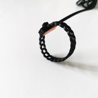
| 1. Ring-lug assembly bolted to a heat sink | no mounted figure published | 14 °C low on a 60.3 °C heat sink in one test; the lug itself was within 2 °C of the sink | Texas Instruments SNIA053 |
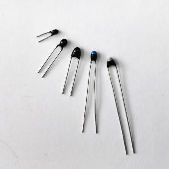
| 2. Epoxy bonded with thermally conductive epoxy | about 0.4 to 1 s | about 0.9 to 2.2 °C low | our calculation, epoxy at 1.3 W/m·K |
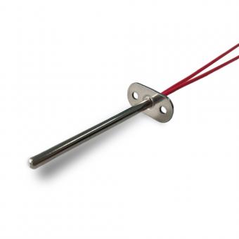
| 3. Insertion probe: bare bead immersed in oil | about 1.2 s (15 s thermal time constant, medium not stated) | no surface-to-air split; a shallow tip reads toward the fitting | Vishay NTCLE100E3 |
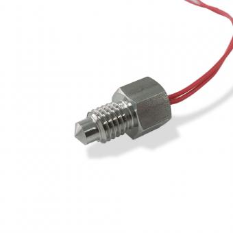
| 4. Threaded fitting or sealed capsule in water | 13 to 16 s from 25 °C air into boiling water; 30 s or less in water at 0.4 m/s | small when the tip sits well inside the flow | Vishay NTCAIMME3; our MFP-7 threaded sensor |
Calculated rows are best cases: the model leaves out the bead's own coating, so real joints are a little slower and read a little lower. None of the figures in the table is a measurement made for this article.
A mounted thermistor settles at a temperature between two heat paths: the path from the surface or fluid you want to measure, and the path from the element to the surrounding air through its body and leads. TDK lists the mounting configuration (immersed or surface-mounted) and the surrounding medium next to sensor design as the main influences on a thermistor's thermal time constant, and states that its published thermal figures refer to still air (TDK NTC thermistors, general technical information).
A single-node heat balance turns that into two formulas (our derivation; TDK gives the matching relation between time constant, heat capacity and dissipation factor):
Here δ is the dissipation factor to the air in mW/K, from the data sheet; G is the thermal conductance of the joint to the target in mW/K; and C is the heat capacity of the sensor in mJ/K.
For the Vishay NTCLE100E3, a common 10 kΩ epoxy-coated bead with copper leads, the data sheet gives a 15 s thermal time constant and a 7 mW/K dissipation factor, so C is about 105 mJ/K (Vishay NTCLE100E3; C is our calculation). Assume the bead touches the surface over a 2 mm × 2 mm patch with a gap of 0.02 to 0.05 mm. Filled with air (0.0262 W/m·K at 25 °C), that gap passes about 2.1 to 5.2 mW/K; filled with a 0.7 W/m·K silicone compound it passes about 56 to 140 mW/K (conductance = conductivity × area ÷ gap, our calculation). With the dry joint the bead settles about 20 to 27 °C below the 60 °C surface, because its body and leads lose more heat to the air than the joint brings in. With compound the offset falls to about 1.7 to 3.9 °C and the time constant falls from about 9 to 12 s to 0.7 to 1.7 s.
The fast end of that range is optimistic. In oil, where liquid surrounds the whole bead, Vishay gives a response of about 1.2 s, and a surface joint is unlikely to beat full immersion because the bead's coating sits in series with either path.
Two conclusions hold whatever the exact geometry. A larger G makes the sensor faster and more accurate at the same time, because both formulas share the same denominator. A smaller δ cuts the offset in proportion: a small glass bead with fine leads, insulation laid over the sensor, or leads run along the surface before they leave it. TDK names size, shape and leads as what sets δ (TDK).
The mounting error can easily exceed the sensor's own tolerance. A standard ±1 % 10 kΩ NTC is about ±0.2 °C at 25 °C (NTC vs PTC vs RTD vs thermocouple table), so a 2 to 4 °C joint error is 10 to 20 times the tolerance you paid for.
Real assemblies show offsets of this size. In a Texas Instruments heat-sink test, a ring-lug NTC read 46.3 °C while a thermal camera showed the heat sink at 60.3 °C and the lug itself at 58.8 °C, and TI names the lug itself and the thermally conductive epoxy inside it as the two main factors, with the epoxy as the biggest (TI application note SNIA053, June 2023). That is one assembly in one test, and TI was comparing it with a silicon sensor it sells, but it shows that the joint inside a bought sensor matters as much as the joint you make. Choose the mount for its heat path first and for convenience second.
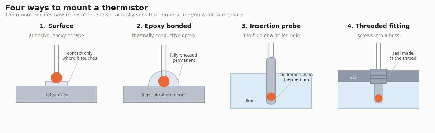
The four methods differ in what fills the space between the element and the thing being measured, and that is what sets their response time and error.
Thermal paste matters on every surface mount because air conducts heat poorly. A silicone compound conducts about 27 times better than air (0.7 against 0.0262 W/m·K at 25 °C), so a gap that is mostly air passes only a small part of the heat the same gap would pass when filled (our calculation from the figures below).
| Joint filler | Thermal conductivity | Relative to air | Source |
|---|---|---|---|
| Air (dry joint) | 0.0262 W/m·K (at 25 °C) | 1 | Engineering ToolBox |
| Silicone heat transfer compound (MG Chemicals 860) | 0.7 W/m·K | about 27 | MG Chemicals 860 |
| Thermally conductive epoxy (MG Chemicals 8329TCM) | 1.3 W/m·K | about 50 | MG Chemicals 8329TCM |
| High-conductivity thermal grease (MG Chemicals 8616) | 2.0 W/m·K | about 76 | MG Chemicals 8616 |
| Copper (ring-lug body) | 385 W/m·K | about 14,700 | HyperPhysics table |
Tape holds the sensor and, laid over it, shields it from moving air, which lowers δ. It does not fill the gap underneath. Put compound under the sensor and tape over it, rather than relying on tape alone. Aluminium tape (205 W/m·K for aluminium in the HyperPhysics table) also spreads heat from the surface around the sensor; polyimide tape mainly holds it in place.
The same split shows up in electronics test work. For a power-supply test from −55 to +85 °C, polyimide (Kapton) tape over a dab of thermal paste holds a probe well and comes off cleanly. Epoxy and general glues are a poorer choice once the surface runs hot. Either way, insulate the exposed side of the sensor, or a surface reading can carry a large error.
Use the thinnest layer that fills the gap. The joint conductance is divided by its thickness, so a thick blob of compound gives back part of what it gained. A higher-conductivity grease helps less than the table suggests once the joint already passes far more heat than the sensor loses to the air: in the worked example, going from 0.7 to 2.0 W/m·K improves the reading by about 1 to 2.4 °C (our calculation).
The order of fixes matters more than the choice of grease. In the worked example, insulation laid over the sensor (modelled as halving δ) does little while the joint is dry and halves the remaining error once the joint is filled:
| Surface mount in the worked example | Reading error on a 60 °C surface in 25 °C air |
|---|---|
| Dry joint, sensor exposed to the air | about 20 to 27 °C low |
| Dry joint, insulation over the sensor | about 14 to 22 °C low |
| Compound in the joint, sensor exposed | about 2 to 4 °C low |
| Compound in the joint, insulation over the sensor | about 1 to 2 °C low |
Our calculation with the single-node model and inputs from the first section. If you can change only one thing on a surface mount, add compound; then insulate over the sensor.
A heated 3D-printer bed shows the effect of covering a sensor. A small sensor laid bare on a glass bed reads well below the bed temperature. Lay a piece of insulation over it and the gap shrinks to a fraction of what it was, which is the direction the table gives.
A response time or thermistor time constant on a data sheet describes one test, not your mount. The same part can carry figures about 20 times apart depending on the medium:
| Part | Figure | Test condition | Source |
|---|---|---|---|
| Vishay NTCLE100E3, epoxy-coated bead | 15 s | thermal time constant (medium not stated) | Vishay |
| Vishay NTCLE100E3 | about 1.2 s | response time in oil | Vishay |
| Vishay NTCAIMME3, NTC in a stainless capsule | 285 s | thermal time constant in still air | Vishay |
| Vishay NTCAIMME3 | 13 to 16 s | 63.2 % of a step from 25 °C air into boiling water | Vishay |
| Vishay NTCAIMME3 | 7.5 and 18 mW/K | dissipation factor in still air and in still water | Vishay |
| Focusens MFP-2 ring lug, MFE-1 pipe clamp, MFP-7 threaded, MFT plastic-housed | 30 s or less | time constant in water at 0.4 m/s | our MFP-2, MFE-1, MFP-7 and MFT pages |
Our own catalogue shows the limit of these numbers. The ring-lug, pipe-clamp and threaded probes all carry the same 30 s water figure, although ring lugs and pipe clamps are not used in water. The figure compares housings under one test. It does not tell you how fast a ring lug bolted to a heat sink will follow, which depends on the joints described above.
A ring lug on a heat sink shows the size of that. Bolt a ring-lug NTC to one face of an LED heat sink and press a bead NTC into a drilled hole on the other, and the bead will lead the ring lug by a few seconds on a power step. Part of that lag is heat crossing the sink, so it is an upper bound for the mount alone.
Also check which point on the step the figure refers to. The time constant (τ, or T63) is the time to 63.2 % of a step; T90, the time to 90 %, is about 2.3 times τ for a first-order sensor, and T50 is about 0.69 times τ (our calculation from the exponential response TDK describes). A 30 s time constant therefore means about 69 s to reach 90 %. Our thermistor vs thermocouple comparison and thermistor assembly selection guide list more figures by package and housing. Ask for the figure in the medium you will use, or for the dissipation factor in that medium, before you compare two probes.
Choose by what you need to measure first, then by whether the sensor must come off again.
| What you measure | What you need | Method |
|---|---|---|
| A liquid in a pipe or tank under pressure | the fluid temperature with a seal | 4. Threaded fitting, such as our MFP-7 or SUS316 threaded probe |
| A liquid you can reach without pressure | the fastest response | 3. Insertion probe with the tip well immersed |
| A solid part you can drill | response close to immersion | 3. Insertion probe in a compound-filled hole |
| A flat metal part with a screw point | removable and repeatable | 1. Surface mounting: ring lug with compound, such as our MFP-2 |
| A pipe, from outside only | no cutting into the pipe | 1. Surface mounting: pipe clamp or strap, such as our IP68 pipe clamp sensor or MFE-1 |
| A vibrating part with no screw point | permanent fixing | 2. Epoxy bonding with a thermally conductive epoxy |
Choosing the body of a surface sensor (ring lug, flat pad or pipe clamp) is a separate decision from how you fix it. The element sets the resistance curve and the tolerance, while the mount sets the response time and most of the error; our NTC thermistor guide covers R25, the B value and self-heating.
Focusens builds ring-lug, pipe-clamp and threaded NTC assemblies to order. Our ISO 9001:2015 and IATF 16949:2016 certificates are on the certifications page. To get a quote, send the surface or fluid, the temperature range, the response you need and how the sensor will be fixed through our contact page.
Put the thermistor where the temperature you want to control is, with the shortest heat path to it: in the fluid for a fluid temperature and on the part for a part temperature, away from drafts and other heat sources. On a surface, insulate over it so it does not read the air.
Thermal paste is needed on any surface mount. Air conducts about 0.026 W/m·K at 25 °C and a silicone compound about 0.7 W/m·K, so filling the gap lets about 27 times more heat through it (our calculation from Engineering ToolBox and MG Chemicals figures). In the worked example that cut the offset from about 20 to 27 °C to under 4 °C. A probe immersed in a liquid does not need it; a probe in a drilled hole does.
A thermistor's response time depends on the package and the medium more than on the thermistor itself. Published figures for one epoxy bead run from about 1.2 s in oil to a 15 s time constant (Vishay NTCLE100E3), and an NTC in a stainless capsule needs 13 to 16 s from air into boiling water but has a 285 s time constant in still air (Vishay NTCAIMME3). Read the medium and the percentage, 63 % or 90 %, next to the number.
Wiring direction does not matter for a two-lead NTC, because it is a resistor without polarity. Wiring errors come from lead and contact resistance, which our thermistor wiring guide covers.
A mounted thermistor can be reused if it was clamped, screwed or threaded in and is undamaged. Clean off the old compound and apply fresh compound before refitting it. Old paste can set hard: grease left in a hot-end thermistor hole can harden and trap the sensor, so use a small dab on the tip rather than filling the hole. An epoxy-bonded sensor usually cannot be removed without damaging it.
A threaded thermistor should be tight enough to seal, and tightened to the torque on the probe's drawing where one is given. Over-tightening can distort the housing or the seat.
Sensor figures come from the Vishay, TDK and Texas Instruments documents linked in each section; joint conductivities from Engineering ToolBox, HyperPhysics and the MG Chemicals data sheets; Focusens figures from our product pages. Figures marked "our calculation" use the single-node model in the first section with the inputs stated there. None of the figures on this page is a measurement made by Focusens for this article.
No.1 XiSan Road, Electromechanical Industry Park , High&New Tech.Zone. Hefei,Anhui,China
tél : +86-551-69109668
Whatsapp : +86-13339100504
e-mail : info@focusens.com
Skype : melodyliu520






 +86-551-69109668