Thermistor Assembly: 5 Interfaces That Decide Survival
Jul 31, 2026A buyer asks for a 10 kΩ NTC probe rated to 150 °C. What arrives is an assembly in which the bead is comfortable at 150 °C, the epoxy is at its published edge, the PVC-jacketed lead is well past its rating, and the crimp is the part that will actually open. Four of those five regions are on a datasheet somewhere. One is not.
| Interface | Governs | Dominant failure mode | How it is verified |
|---|---|---|---|
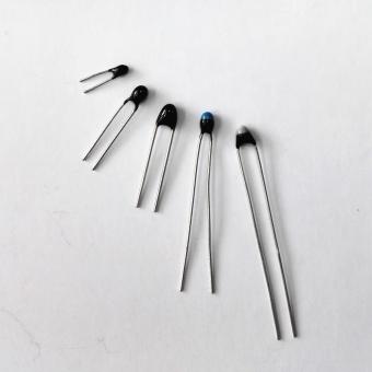
| Element | R25, B constant, tolerance band, curve shape | Slow resistance drift under long hot or humid service; rarely sudden | R–T table or Steinhart–Hart coefficients, plus a stated tolerance and the band it applies over |
| Encapsulation | Moisture barrier, upper temperature, thermal mass | Water reaching the ceramic–electrode interface; cracking at material boundaries under cycling | Damp-heat and temperature-change exposure — the conditions matter more than the pass/fail |
| Lead wire | Temperature limit, flex life, chemical and abrasion resistance | Insulation softening, cracking, or abrading through where the cable crosses an edge | UL style number and the manufacturer's certificate for that style |
| Joint | Mechanical and electrical continuity between fine element leads and the extension conductor | Intermittent open under vibration or thermal cycling | Destructive pull test on a sample basis — see below |
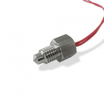
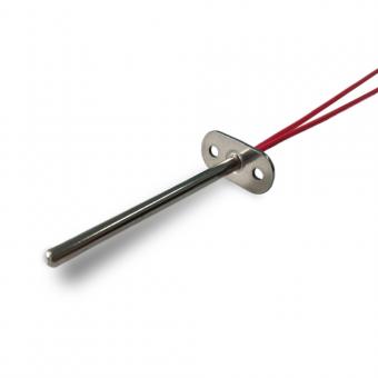
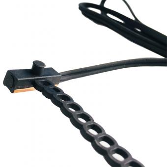
| Housing | Thermal coupling to the process, ingress protection, mechanical protection | Slow or damped response; seal failure at the cable entry | Material and mounting interface on a drawing; ingress by test report with its conditions |
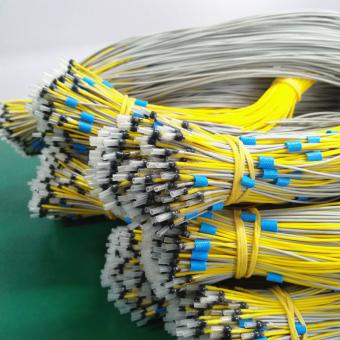
The joint is where a fine element lead — frequently a different metal from the extension conductor — meets the cable. Welded, soldered, crimped and ultrasonically bonded joints all work in production and all fail differently. A joint that passes a bench continuity check can still open intermittently after a few thousand thermal cycles, and an intermittent open in a control loop presents as a sensor fault long before anyone suspects a mechanical one.
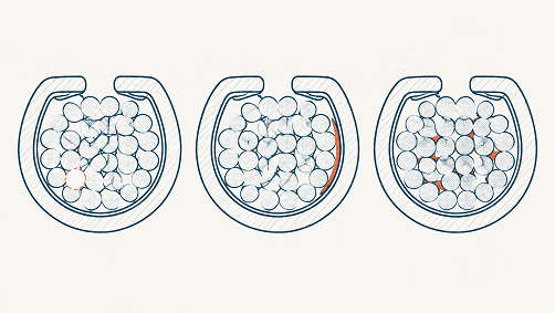
There is an industry framework for this, and buyers can quote it directly. IPC/WHMA-A-620, Requirements and Acceptance for Cable and Wire Harness Assemblies, sets out three acceptance classes and, in its Chapter 19, defines pull-force testing, crimp-height measurement and crimp-force monitoring. It also sets inspection conditions that are easy to check on a factory visit: magnification is graded by conductor size — conductors above roughly 1.63 mm (14 AWG) may be inspected unaided, 1.63 mm down to 0.64 mm (14–22 AWG) require about 1.5× to 3×, and finer gauges of 24–30 AWG require roughly 4× to 10× — with illumination of at least 1000 lux.
Practical consequence: do not put a pull-force number on your drawing copied from a web page. Put the authority on the drawing — "pull force per terminal manufacturer's specification, verified per IPC/WHMA-A-620 Class 2" — and ask the supplier to state which table and which value they test to. Sources consulted 2026-07-30; see Claim Ledger.
A crimp that measures below the specified force still passes visual inspection every time. That is the whole reason the test exists.
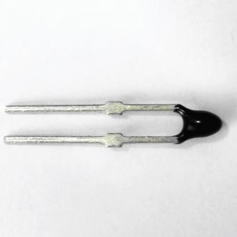
Consider a probe specified for a 150 °C process. The bead itself is a metal-oxide ceramic and is thermally comfortable well above that. The encapsulation is a polymer with a published continuous rating that may sit close to 150 °C. The lead insulation has a rating that depends on its UL style rather than on the polymer family name — the same "PTFE" designation appears in published listings at 200 °C, 250 °C and 260 °C depending on the construction. The joint has no rating at all, only a test. And the housing determines whether the element ever reaches process temperature in the first place.
Stack those and the binding constraint is usually the third or fourth item, not the first. This is also why "rated to 150 °C" is not a specification: it does not say which part is rated to 150 °C.
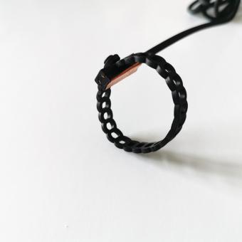
A metal housing couples the element to whatever it touches and adds thermal mass. A moulded or overmoulded body isolates slightly and adds less. Neither is better in the abstract. A probe in a stirred liquid wants coupling; a probe reading a surface through a clamp wants the smallest thermal mass available, or it averages away the thing it is measuring.
If a reading lags the process, the housing is the first suspect and the element is the last — mass and contact area dominate the time constant, and no element substitution recovers a housing that is too heavy for the loop. Overmoulded bodies also change the sealing question, because the seal is formed rather than assembled; the overmoulding guide covers that trade-off. Once the probe is fitted, how it is held against the surface takes over from the housing design — that is the subject of our guide to fitting practice.
Most enquiries specify the element and leave the other four interfaces to the supplier's default. That is how a probe with the correct resistance curve arrives with the wrong cable.
If you can answer all six lines, a supplier can quote a build rather than a catalogue part. If two of them are blank, those two are where the last sensor problem came from.
Send the six lines and get a build proposal →
Source note. No dimension, temperature limit, pull-force value or lead time is asserted for any Focusensing product in this article. Acceptance-standard content is described at the level of what the standard covers, not reproduced from it. Where a figure matters to your design, request it in writing against a part code — several parameters across the range are not reconciled between the catalogue and individual product pages.
No.1 XiSan Road, Electromechanical Industry Park , High&New Tech.Zone. Hefei,Anhui,China
tél : +86-551-69109668
Whatsapp : +86-13339100504
e-mail : info@focusens.com
Skype : melodyliu520






 +86-551-69109668