NTC thermistor guide: B value, resistance curve and selection
Sep 03, 2026An NTC thermistor is a temperature sensor whose resistance falls as it heats up. NTC stands for negative temperature coefficient. It is made from sintered metal-oxide ceramic, and it is described by two numbers: R25, the resistance at 25 °C, and a B value that sets how steeply the resistance falls.
The second of those numbers causes more field problems than any other parameter in thermistor work, because the same physical device can honestly be labelled 3950 or 3988 depending on which two temperatures it was measured between.
This guide covers what that means for your calibration, and what to specify so it does not bite you.
Published 3 September 2026. Reviewed by the Focusens technical department.
Thermistor behaviour is not fixed by a single international curve the way platinum RTDs are. Where a PT100 is interchangeable because IEC 60751 defines one relationship for every compliant part, an NTC follows the curve of its own ceramic formulation.
The generic requirements, terminology and test methods for these devices sit in IEC 60539-1:2022, edition 4.0, published 15 December 2022, covering directly heated negative temperature coefficient thermistors made from transition metal oxide materials.
That difference is the root of everything below. Two thermistors can both be honestly described as “10 kΩ NTC” and follow measurably different curves. The usual working model is the Beta equation:
R(T) = R₂₅ · exp[ B · (1/T − 1/298.15) ]
with T in kelvin and B in kelvin. Rearranged for temperature:
T = 1 / [ 1/298.15 + ln(R/R₂₅) / B ]
The table below is that equation evaluated for a 10 kΩ part with B = 3988 K. It is a model output, not a measured datasheet, and the gap between the two is the subject of the next two sections.
| Temperature | Resistance | Temperature | Resistance |
|---|---|---|---|
| −40 °C | 416.4 kΩ | 50 °C | 3,553 Ω |
| −20 °C | 107.8 kΩ | 60 °C | 2,453 Ω |
| 0 °C | 34.02 kΩ | 70 °C | 1,731 Ω |
| 10 °C | 20.31 kΩ | 80 °C | 1,245 Ω |
| 25 °C | 10,000 Ω | 100 °C | 680 Ω |
| 30 °C | 8,020 Ω | 125 °C | 348 Ω |
| 40 °C | 5,269 Ω | 150 °C | 192 Ω |
Calculated from the Beta equation above, R25 = 10 kΩ, B = 3988 K. Use a manufacturer's own curve data for design work.
B is not a property you can read off a device. It is a number computed from two resistance measurements at two temperatures:
B(T₁/T₂) = ln(R₁/R₂) / (1/T₁ − 1/T₂)
Change either temperature and the answer changes, because a real thermistor curve is not a perfect exponential. That is why a datasheet B value always carries a subscript naming the pair it was taken between. In the Focusens catalogue alone, parts are specified against five different reference pairs.
| Reference pair | Meaning | Example catalogue entries |
|---|---|---|
| B25/50 | measured between 25 °C and 50 °C | 2.19 kΩ B25/50:3470, 50 kΩ B25/50:3950, 100 kΩ B25/50:4150 |
| B25/85 | measured between 25 °C and 85 °C | 2.2 kΩ B25/85:3977, 10 kΩ B25/85:3988, 1 MΩ B25/85:4600 |
| B25/100 | measured between 25 °C and 100 °C | 5 kΩ B25/100:3988 |
| B0/100 | measured between 0 °C and 100 °C | R100 = 3.3 kΩ, B0/100:3970 |
| B100/200 | measured between 100 °C and 200 °C | 231.4 kΩ, R200 = 1 kΩ, B100/200:4537 |
Reference pairs and values from the Focusens product catalogue.
Notice B100/200:4537 against the B25/50 figures around 3470 to 4150. Those are not sloppy specifications. A thermistor's apparent B rises with the measurement temperature because the curve steepens, so a part characterised for a high-temperature application legitimately reports a larger number than a part characterised near room temperature.
Comparing the two as though they were the same parameter is a specification error.
The cost of a mismatched reference pair is measurable, and it is not spread evenly across the range.
Take a 10 kΩ device whose true behaviour follows B = 3988. Suppose your firmware converts resistance to temperature using B = 3950, roughly a 1% difference and a very ordinary mix-up between two datasheet lines. The resulting error is not constant.
| True temperature | Resistance at B = 3988 | Temperature computed with B = 3950 | Error |
|---|---|---|---|
| −20 °C | 107,800 Ω | −20.37 °C | −0.37 °C |
| 0 °C | 34,015 Ω | −0.22 °C | −0.22 °C |
| 25 °C | 10,000 Ω | 25.00 °C | 0.00 °C |
| 50 °C | 3,553 Ω | 50.26 °C | +0.26 °C |
| 85 °C | 1,064 Ω | 85.69 °C | +0.69 °C |
| 105 °C | 590 Ω | 105.98 °C | +0.98 °C |
| 125 °C | 348 Ω | 126.29 °C | +1.29 °C |
Both columns computed from the Beta equation with R25 = 10 kΩ.
Read the middle row first. At 25 °C the error is exactly zero, and it is zero by construction, because 25 °C is the reference point both curves pass through.
Every bench check you run at room temperature will pass. The error only appears as you move away from the reference, reaching about 1.3 °C at 125 °C.
A room-temperature functional test cannot detect a wrong B value. If your validation plan has one temperature in it, it has a blind spot exactly where the sensor is most likely to be wrong. The same arithmetic sets the sensitivity to B tolerance generally.
For a device referenced at 25 °C, a 1% error in B produces roughly +0.23 °C at 0 °C, about −0.39 °C at 60 °C, and about −0.93 °C at 100 °C.
B tolerance is usually quoted alongside R25 tolerance, and away from the reference point it is often the larger of the two.
The Beta model uses one exponential to describe a curve that is not exactly exponential. It is accurate near the reference pair and drifts outside it, which is exactly the behaviour the table above demonstrates.
For wider spans, the standard alternative is the Steinhart–Hart equation, published by John Steinhart and Stanley Hart in 1968 in Deep-Sea Research as “Calibration curves for thermistors”:
1/T = A + B·ln(R) + C·(ln R)³
Three coefficients replace one, so the fit follows the real curve over a much wider range. You obtain them by measuring resistance at three temperatures spread across your working range and solving the three simultaneous equations, or by fitting to a manufacturer's tabulated curve.
Use the Beta equation when your span is narrow, sits close to the reference pair, and a few tenths of a degree at the edges is acceptable.
Use Steinhart–Hart when the span is wide, when accuracy has to hold at both ends, or when you are already storing calibration coefficients per unit. The cost is three coefficients in firmware and a cube in the conversion, which is negligible on any modern microcontroller.
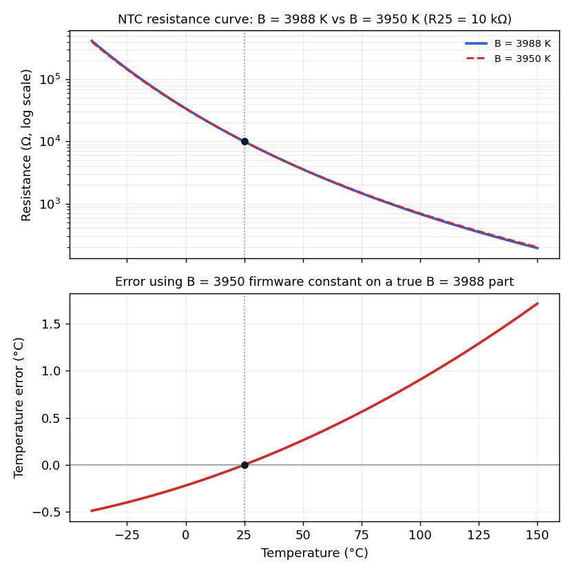
Computed from the Beta equation with R25 = 10 kΩ. The error crosses zero at the reference point, which is why a room-temperature check does not reveal it.
Measuring a thermistor requires passing current through it, and that current heats it. The sensor then reports its own dissipation as process temperature. The error is the dissipated power multiplied by the device's dissipation constant, usually quoted in mW per °C.
Dissipation constant is not a property of the ceramic alone, because it depends on how well the surroundings carry heat away. A bead in still air runs hotter than the same bead in flowing water at the same current, sometimes by a large factor.
Two consequences for circuit design. Pick the excitation current from your error budget, not from what the ADC finds convenient, and remember that a 100 kΩ part at a given voltage dissipates a tenth of what a 10 kΩ part does.
Pulse the excitation if the budget is tight: energise the divider, settle, sample, then turn it off, so average dissipation drops by the duty cycle.
Ask for the dissipation constant in the medium you will actually use. A number measured in still air does not describe a probe clamped to a battery tab.
Five decisions cover most NTC thermistor selection.
| Decision | Typical range | What drives it |
|---|---|---|
| R25 | 2 kΩ to 1 MΩ in standard values | ADC input impedance, divider design, self-heating budget |
| B value and reference pair | roughly 3400 to 4600 K | your operating span, and it must be quoted against the pair you will calibrate against |
| Tolerance | 0.5% to 5% on resistance | the accuracy you need without per-unit calibration |
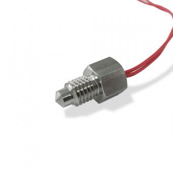
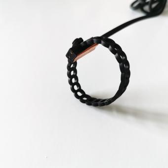
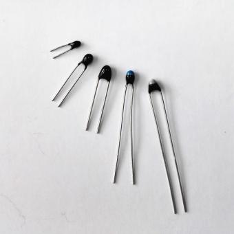
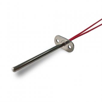
| Package | epoxy bead, glass encapsulated, surface mount chip, probe assembly | ambient, moisture, mounting method, response time |
| Interchangeability | standard tolerance, or matched to a curve | whether units can be swapped without recalibrating |
Focusens NTC elements are available with R25 from 50 Ω to 2 MΩ and B values from 3900 to 4800 K, with accuracy from 0.5% to 5% and interchangeable grades quoted from ±0.1 °C to ±2 °C on request.
Common stocked values include 2.2 kΩ B25/85:3977, 5 kΩ B25/85:3977, 10 kΩ B25/85:3988, 50 kΩ B25/50:3950 and 100 kΩ B25/50:4150. Specifications from the Focusens product catalogue.
Two selection rules that save trouble later. Choose R25 so your divider output sits in the middle of the ADC range across your actual span, not at 25 °C, because an exponential curve moves a long way.
And write the reference pair into the purchase specification, not just the B number, so that “3950” cannot arrive as B25/50 when your firmware assumed B25/85.
Once the element is chosen, how it is mounted decides your response time and a good deal of your accuracy. The practical side of that is in thermistor mounting best practices.
Both are thermistors, and they do opposite jobs.
| NTC | PTC | |
|---|---|---|
| Resistance with rising temperature | falls | rises |
| Curve | smooth exponential | flat, then a steep rise past a switching point |
| Main use | measuring temperature | protection, switching, current limiting |
| Typical placement | signal input to a controller | in a power path, or embedded in a motor winding |
If the part feeds a reading to a control board, it is almost certainly NTC. If it sits in series with a load or buried in a motor winding, it is almost certainly PTC. How to identify NTC and PTC thermistors covers telling them apart when the part is unmarked.
Failures divide into two groups, and only one of them is obvious. Hard failures show as an open circuit from a cracked bead or a broken lead, or as a near short from moisture bridging the leads or a crushed cable. A meter finds these immediately.
Drift is the difficult one. Metal-oxide ceramic changes slowly under sustained high temperature and under repeated thermal cycling, and a drifted thermistor still reads a plausible resistance.
It fails no continuity test and it passes a bench check at room temperature, for the same reason a wrong B value does: the deviation grows with distance from the reference point. Catching drift needs a two-point check, one near ambient and one near the working temperature.
Moisture is the most common preventable cause. An epoxy-coated bead in a humid enclosure absorbs water over months, and the resistance shifts before anything visibly fails. Glass encapsulation is the usual answer where humidity is a real risk.
The step-by-step procedure, including what each reading pattern means, is in how to test an NTC thermistor with a multimeter.
Choose an NTC when the span is narrow, resolution near ambient matters, and unit cost is under pressure. Choose a platinum RTD when the span is wide, when the sensor has to be replaceable without recalibrating the instrument, or when a specification has to cite a standard.
The full comparison and the RTD side of the selection is in the resistance temperature detector guide. Focusens NTC elements and probe assemblies are listed in the NTC thermistor category.
The resistance table and the error table are computed from the Beta equation printed on this page, with the parameters stated above each table. They demonstrate how the model behaves.
They are not measured data for any specific part, and a real device deviates from a single-B model away from its reference pair, which is the point the Steinhart–Hart section makes.
R25 ranges, B values, reference pairs and tolerance grades quoted as Focusens specifications come from the product catalogue. This guide does not assert a dissipation constant, a drift rate or an interchangeability figure for any specific part.
Those are per-part values measured in a stated medium, and they should be requested against a part code.
No.1 XiSan Road, Electromechanical Industry Park , High&New Tech.Zone. Hefei,Anhui,China
tél : +86-551-69109668
Whatsapp : +86-13339100504
e-mail : info@focusens.com
Skype : melodyliu520






 +86-551-69109668