KTY83-110 equivalent: cross-reference and replacement guide
Sep 08, 2026The KTY83-110 is a silicon PTC temperature sensor with a nominal 1000 Ω at 25 °C in a hermetic glass axial package. NXP has discontinued the KTY8x family and states plainly that it has no replacement offering of its own.
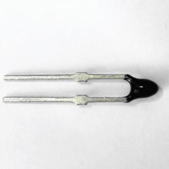
The Focusens LPTC83-110 matches it electrically at R25 = 1000 Ω over the same −55 to +175 °C range, in a DO-35 glass body rather than the KTY's DO-34.
That package difference is the one detail that decides whether your existing board takes the part without a change. It is covered below, with the full family cross-reference.
Published 10 September 2026. Reviewed by the Focusens technical department.
NXP's product page for the silicon temperature sensors carries the notice that this is a product that is no longer manufactured.
On that page NXP names KTY82 and KTY81 as end of life and not recommended for new designs, with last order shipment on 31 March 2026, and directs customers to Rochester Electronics to check remaining stock.
Two things follow that matter for a buying decision. The last-order window for the parts NXP names has already closed, so what remains in distribution is legacy stock at broker pricing rather than production supply.
And NXP states it has no replacement offering, which means any drop-in claim you read comes from a third party rather than from the original manufacturer.
Ask a search engine for a KTY83-110 replacement today and the answer block returns −55 to +150 °C, sourced from a distributor listing. NXP's own KTY83 series datasheet, Rev. 06, dated 4 April 2008, gives the ambient temperature range as −55 to +175 °C.
The difference is not academic. An engineer specifying a replacement for a 160 °C winding or a 165 °C process would read the circulating figure, conclude the KTY83 route is closed, and go looking at a different technology.
The manufacturer's datasheet says otherwise, and the Focusens LPTC83 series is specified to the same −55 to +175 °C, so two independent documents agree against the widely repeated figure. Where a number matters, take it from the datasheet rather than from a listing.
| Parameter | Value |
|---|---|
| Sensor resistance R25 | 990 / 1000 / 1010 Ω (min / typ / max) at Isen = 1 mA |
| Ambient temperature range | −55 to +175 °C |
| Package | SOD68 (DO-34), hermetically sealed glass, axial leads |
| Temperature coefficient at 25 °C | 0.76 %/K |
| R100 / R25 ratio | 1.65 / 1.67 / 1.69 (min / typ / max) |
| Recommended sensor current | 1 mA continuous |
All values from NXP KTY83 series datasheet Rev. 06. The datasheet notes that 1 mA is recommended to keep temperature error low above 100 °C.
Before committing a substitution, verify the curve rather than the endpoints. The NXP datasheet carries a resistance-versus-temperature table for the KTY83 series at 1 mA; check it against the LPTC curve for the same part at the temperatures your design actually operates at, not just at 25 °C.
Two parts can share R25 = 1000 Ω and still diverge at the ends of the range, and R25 alone will not reveal it.
| Obsolete NXP part | R25 or R100 | Focusens equivalent | Tolerance options | Rated range |
|---|---|---|---|---|
| KTY83 1 kΩ series | R25 = 1000 Ω | LPTC83-110 / -120 / -121 / -122 / -150 / -151 / -152 | ±1%, ±2%, −2%, +2%, ±5%, −5%, +5% | −55 to +175 °C |
| KTY81 1 kΩ series | R25 = 1000 Ω | LPTC81-110 / -120 / -121 / -122 / -150 / -151 / -152 | ±1%, ±2%, −2%, +2%, ±5%, −5%, +5% | −55 to +150 °C |
| KTY81 2 kΩ series, KTY10-5 / -6 / -62 / -7 | R25 = 2000 Ω | LPTC81-210 / -220 / -221 / -222 / -250 / -251 / -252 | ±1%, ±2%, −2%, +2%, ±5%, −5%, +5% | −55 to +150 °C |
| KTY84 series | R100 = 1000 Ω | LPTC84-130 / -150 / -151 / -152 | ±3%, ±5%, −5%, +5% | −40 to +180 °C |
Cross-reference from the Focusens LPTC series datasheet. Note that the KTY84 line is specified at R100 rather than R25, because that family is characterised for higher-temperature service; do not compare its number against an R25 figure.
The suffix carries the tolerance. A part ending in 110 is ±1%, 120 is ±2%, 121 is −2% one-sided, 122 is +2% one-sided, 150 is ±5%, 151 is −5% and 152 is +5%.
One-sided grades exist because some designs only care about drift in one direction, and they are usually cheaper than the symmetric grade.
Where no KTY equivalent applies, the LPTC series also covers R25 = 200, 500, 1200 Ω over −40 to +150 °C and R25 = 1600, 3800, 4050 Ω over −50 to +125 °C.
This is where a replacement either works or costs you a board revision.
| NXP KTY83-110 | Focusens LPTC | |
|---|---|---|
| Outline | SOD68, equivalent to DO-34 | DO-35 |
| Body diameter | per NXP datasheet | 1.85 mm max |
| Body length | per NXP datasheet | 3.85 mm max |
| Lead length | per NXP datasheet | 28 mm max |
| Lead diameter | per NXP datasheet | 0.5 ± 0.05 mm |

LPTC dimensions from the Focusens datasheet. The KTY outline is shown to its published designation. Check both against your own footprint before substituting.
LPTC dimensions from the Focusens LPTC series datasheet. The KTY83-110 outline is given as SOD68, equivalent to DO-34, in NXP's datasheet. DO-34 and DO-35 are different registered outlines, so the LPTC is an electrical equivalent rather than a guaranteed mechanical drop-in.
Compare the two body envelopes against your own footprint drawing rather than assuming the axial form makes them interchangeable. In practical terms, a through-hole axial position with formed leads usually accepts either, because the lead span is set when you form the leads.
A position with a tight body pocket, a clip, a moulded retainer or an automated insertion programme set for DO-34 is where the difference shows up. Check the body envelope against your footprint before committing, and request samples against your actual fixture rather than against the drawing.
Silicon PTC sensors are also polarity-sensitive in operation, unlike a ceramic PTC or an NTC bead. Keep the original orientation when you swap.
| Parameter | Value | Condition |
|---|---|---|
| Dissipation factor | 2.5 to 5 mW/°C | still air |
| Thermal time constant | 8 to 10 s | still air |
| Thermal time constant | 1.1 to 1.2 s | stirring water |
| Maximum power | ≤100 mW | |
| Maximum current | 1.0 mA |
From the Focusens LPTC datasheet. The two time constants are the same part measured in two media, which is why they differ by a factor of about eight; quote the medium whenever you quote a response time, and never compare a still-air figure against a moving-water one.
Note that maximum current is 1.0 mA and the NXP datasheet recommends 1 mA for the original part. If your existing circuit drives the sensor at its recommended current, it is already at the LPTC's ceiling rather than below it, so check the actual excitation in your design rather than assuming headroom.
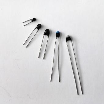
A like-for-like electrical swap on an existing board. Match R25 and the rated range, then verify the body envelope. LPTC83-110 against a KTY83-110 keeps R25 = 1000 Ω and the full −55 to +175 °C span. The LPTC linear silicon PTC in DO-35 glass is the base part.
A new design that no longer has to honour the KTY curve. You are free to choose on merit, and a platinum RTD gives a standardised curve and wider range at higher cost and with different scaling.
That is a different conversation from a substitution, and the resistance temperature detector guide covers what changes.
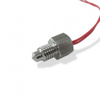
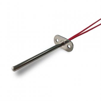
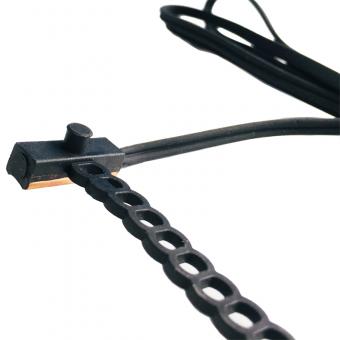
A finished probe rather than a bare element. Where the KTY sat inside an assembly, the FTY series silicon PTC sensor and the EV motor protection variant package the same silicon PTC into a housing and lead set.
The full family sits under linear PTC silicon thermistors, with finished probes under linear PTC silicon thermistor sensors.
Tolerance grade against the one the original design assumed, since a −5% one-sided part is not interchangeable with a ±1% part in a circuit that was calibrated around the symmetric grade.
Body envelope against the footprint, per the package section above. Excitation current against the 1.0 mA ceiling. Polarity and orientation.
And for anything carrying a safety or compliance function, the substitution needs first-party documentation for the new part rather than an equivalence claim, because a cross-reference table establishes electrical similarity and nothing else.
Once the replacement is in hand, the bench check is the same one you would run on any silicon PTC: resistance rises with temperature, and the change is gradual rather than a switching step. The procedure is in how to test a PTC thermistor with a multimeter.
No.1 XiSan Road, Electromechanical Industry Park , High&New Tech.Zone. Hefei,Anhui,China
tél : +86-551-69109668
Whatsapp : +86-13339100504
e-mail : info@focusens.com
Skype : melodyliu520






 +86-551-69109668